Your product
1700/1750 - Abrasive grain feeder attachment 355


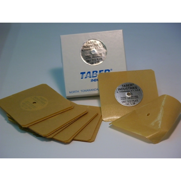


1700/1750 - Abrasive grain feeder attachment 355
Das Taber Grit Feeder Attachment 355 (Schleifkorn-Zuführaufsatz) wird in Verbindung mit dem Taber Rotary Platform Abraser (Abrader) 1700/1750 verwendet, um den durch die zerstörende Wirkung feiner, harter Partikel verursachten Dreikörperabrieb zu bewerten. Ursprünglich als Frick-Taber-Test bezeichnet, wurde dieses Instrument zur Bestimmung der Verschleißfestigkeit von Bodenbelägen mit glatten Oberflächen verwendet.
Required accessories relevant ...

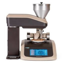 |
The Grit Feeder is a free-standing instrument that has a Taber Rotary Platform Abraser 1700/1750 (nicht im Lieferumfang enthalten) zur Durchführung der Tests benötigt. Die Kornverteilungsdüse wird über der Probe des Taber Abraser vor dem rechten Schleifrad positioniert. Während der Prüfung werden Schleifkörner gleichmäßig und kontinuierlich auf die Probenoberfläche aufgetragen. |
| Wenn sich der Probenhalter dreht, laufen die losen Schleifpartikel unter einem Paar S-39 Leather-Clad Wheels hindurch. Die dabei entstehende Rollbewegung der Partikel dient als Abriebmittel und trägt zur physikalischen Zersetzung des Materials bei. |  |
Nachdem die Sandpartikel unter beiden Rädern hindurchgelaufen sind, werden sie zusammen mit den während des Tests entstandenen Abriebpartikeln durch ein Vakuumsystem entfernt.
The operation of the grain feed is controlled via the Taber Abraser, so that the rotary disc, the grain distribution and the suction are operated simultaneously.
IMPORTANT: Due to the type and quantity of abrasives used in this test, Taber recommends that the vacuum filter and collection bag are checked regularly and replaced as necessary.
Model overview
- Grit Feeder- Model 355 ist speziell für den Einsatz mit dem Taber Abraser Modell 1700 oder 1750 konzipiert. Es bietet einen leicht zu befüllenden Trichter mit einer Kapazität von etwa 2.650 Gramm. Die Trichterbaugruppe des Modells 355 wird entweder auf der linken oder rechten Seite des Taber Abraser montiert und ist schwenkbar, so dass der Bediener einen einfachen Zugang zum Betrachten oder Montieren der Testprobe hat. Die Steuerung und Bedienung des Kornzuführungsaufsatzes erfolgt über das Touchpad des Modells 1700 oder 1750 und das mitgelieferte USB-Schnittstellenkabel. Eine gekrümmte Saugdüse an der Vorderseite, die speziell für die Verwendung mit dem Modell 1700 und 1750 entwickelt wurde, dient zum Entfernen von verbrauchtem Sand und Ablagerungen.
- The Grit Feeder Model 255 kann mit älteren Versionen des Taber Abraser verwendet werden und bietet eine Trichterkapazität von ca. 4.500 Gramm. Im Sockel des Modells 255 ist ein Ausrichtblock integriert, der die korrekte Positionierung der Kornzuführung im Verhältnis zum Abraser gewährleistet. Eine Handkurbel steuert die Teleskopfunktion, die eine präzise Höheneinstellung und die Prüfung dickerer Proben (bis zu 40 mm mit dem Taber Abraser Arm Height Extension Kit) ermöglicht. Durch die Möglichkeit der Montage auf der rechten oder linken Seite können zwei Instrumente in Verbindung mit dem Taber Abraser mit doppelter Drehplattform verwendet werden.
Note: A Grit Feeder Control Box (sold separately) is required to use older versions of the Taber Grit Feeder with Taber Abraser Model 5135 or 5155 equipped with the Grit Feeder Control Output port.
Abrasive
The standardised abrasive that is supplied with the Taber Grit Feeder is a #240 Aluminium oxide grain (model S-41). Dieses speziell für Taber Industries hergestellte Aluminiumoxid weist im Vergleich zu “Aluminiumoxid von der Stange” strengere Kontrollen für die Partikelgrößenanalyse und die Schüttdichteeigenschaften auf.
| Zur Kalibrierung der Durchflussrate und zur Messung der Abtragsrate des Schleifmittels werden S-38 Standardisierungsplatten used. |  |
Before use, the Abrasive grit durch das US-Standardsieb Nr. 80 gesiebt werden, um etwaige Konglomerate aufzubrechen und übergroße oder fremde Partikel zu entfernen. Anschließend wird das Schleifkorn 1 Stunde lang bei ca. 82° C (180° F) getrocknet. Vor der Verwendung in einem Raum mit kontrollierter Temperatur und Luftfeuchtigkeit abkühlen lassen.
In order to fulfil the EN 14354 and ISO 24338 method B test method, the Aluminium oxide grain Alodur ESK 240 verwendet werden. Kontaktieren Sie uns für weitere Informationen.
Evaluation
The following methods are commonly used to analyse grit feeder test results:
- Weight loss (mass) - The weight loss test method is a quantifiable method that records the weight loss of your test sample due to abrasion. This method of analysing test results is recommended when comparing results to similar materials with nearly the same specific gravity. Weigh your test sample before and after the test to determine the initial and final weight. The difference between these two values, Ftotal, is the weight loss.
Ftotal = A - B
wobei- A = Gewicht (Masse) der Probe vor dem Abrieb, mg
- B = Weight (mass) of the test specimen after abrasion, mg
- Use the following formula to calculate the average mass loss Fm in milligrams (mg) per 100 cycles:
Fm = (Ftotal / n) x 100
wobei- n = Gesamtzahl der Umdrehungen
- The Taber wear index can also be used to visualise weight loss data. This measure is the weight loss in milligrams per thousand abrasion cycles. The lower the wear index, the better the abrasion resistance of the material.
Taber wear index = (Ftotal x 1000) / n - Cycles up to a certain end point - The number of cycles required to reach a specified end point (e.g. wear to substrate). Alternatively, this could be expressed as the state of the specimen after a specified number of cycles.
In accordance with test method EN 14254 (Wood-based panels - Wood veneer floor coverings - Annex D - Test method for the determination of wear resistance), the wear produced by the Taber Grit Feeder is assessed using a transparent template, with each quadrant divided into four sectors of 22.5°. The transparent template is placed on the test piece to determine if there is continuous wear in 12 of 16 sectors and continuous grit in one sector per quadrant. If the contrast between the substrate and the coating is insufficient, a contrast marking solution can be used (e.g. an aqueous solution of 1% methylene blue or alkali blue). - Volume loss method - When comparing the wear resistance of materials with different specific gravities, a correction for the specific gravity of each material should be applied to the weight loss to give a true measure of comparative wear resistance. The application of this correction factor results in a wear index that relates to the volume loss of the material to which it is applied.
Determine the specific gravity of the material to be tested in accordance with standard practice. If the sample is not homogeneous but has a surface that is different from the body or core, determine only the specific gravity of the surface. If the abrasion extends beyond the surface of the body, the specific gravity of the body shall also be determined and the abrasion resistance of the two components shall be calculated and reported separately.
Volume loss, cm3 = (W1 - W2) / S
wobei- W1 – Gewicht des Probekörpers vor dem Abrieb, g
- W2 = Weight of the test specimen after abrasion, g
- S = specific weight
- Abrasion depth method (thickness) - Certain test requirements may require the abrasion depth to be measured. To determine this, mark four points on the back of an unabraded specimen 90° apart and at a distance of 38 mm (11/2″) from the centre hole [this is within the wear path]. Measure the sample thickness with a thickness gauge or micrometer. After grinding down the sample, repeat the measurements and note the difference. To compensate for differences in depth around the wear path of the sample, an average value should be calculated from the four measured values.
The change in thickness can also be measured using an optical micrometer or similar instrument. Position the gauge so that it covers both the abraded and unabraded portions of the sample. Calculate the wear by measuring the difference between the abraded and unabraded areas at four equally spaced points around the sample and average the results.
Alternatively, the average thickness loss can be calculated by dividing the volume loss by the abraded area of the sample.
Additional information
| brand | Taber |
|---|---|
| Standards | ASTM F510, EN 13696, EN 14354, EN 15468, EN 655, EN 660-2, IKEA Spec. No. IOS-TM-0002, ISO 24338 |
| Mission | Laboratory |